Quinary LED Art Clock 
Sunday, October 11, 2020, 14:30
Posted by Administrator


This quinary ( base 5 ) LED clock project has taken me many more months than I thought it would. I spent a great deal of time considering and ruminating over exactly how I wanted it to look and operate. It's gone through many, many, many iterations but is finally in a 'done' enough state that I feel quite happy with it and ready to write about it and possibly move on to other things in my life.

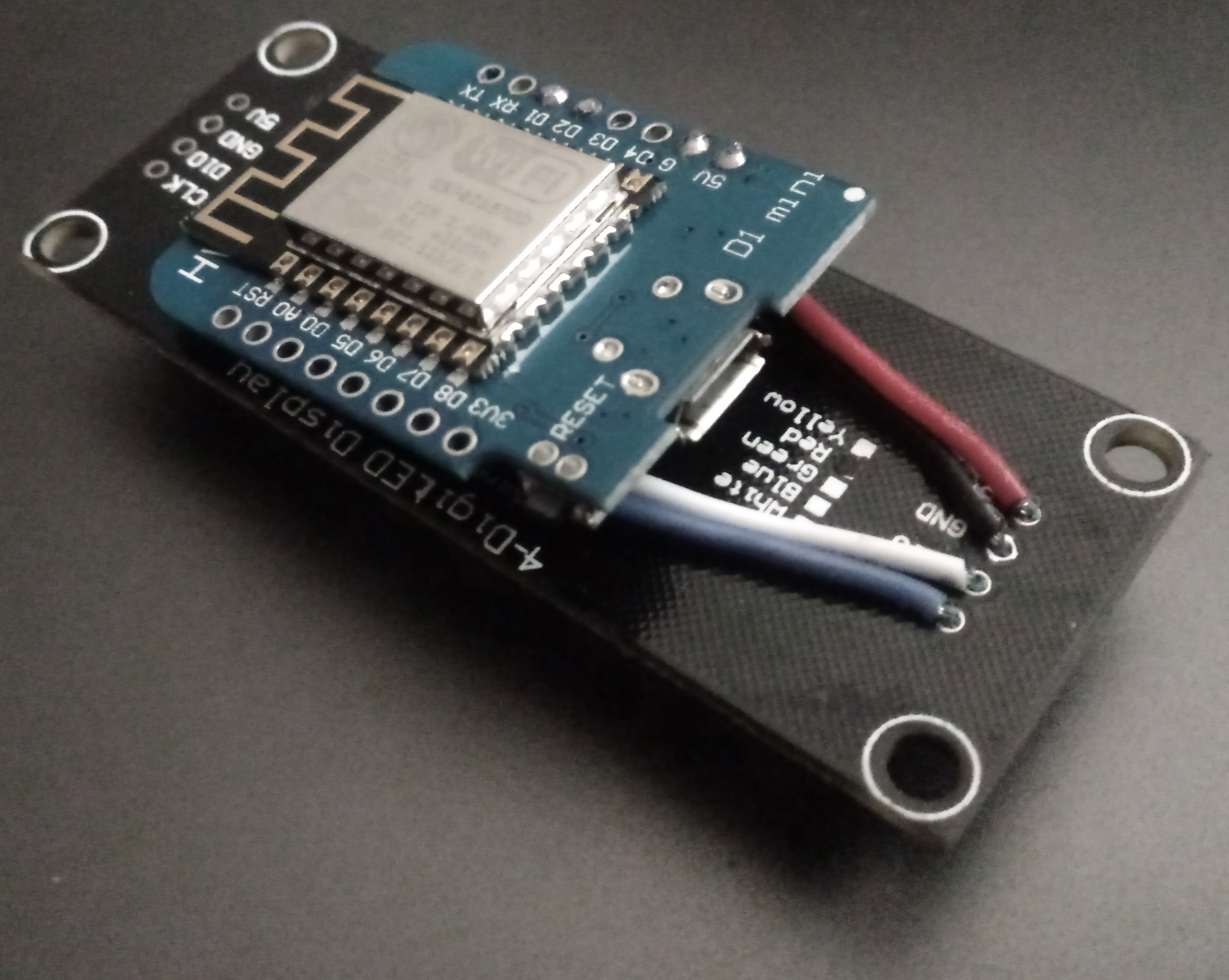
It began first with the concept of utilizing addressable ws2812b LED strips to indicate the time in an alternate base. I've worked on binary clocks a few times in the past but have grown a little tired of the concept, and I wanted to create something that would make more efficient use of fewer LEDs so that I could power them directly from an esp8266 without worrying about drawing too much power from the board itself and burning it out. I like the simplicity of not providing additional current, and I wanted to see how much utility I could sneak out of these power limitations.

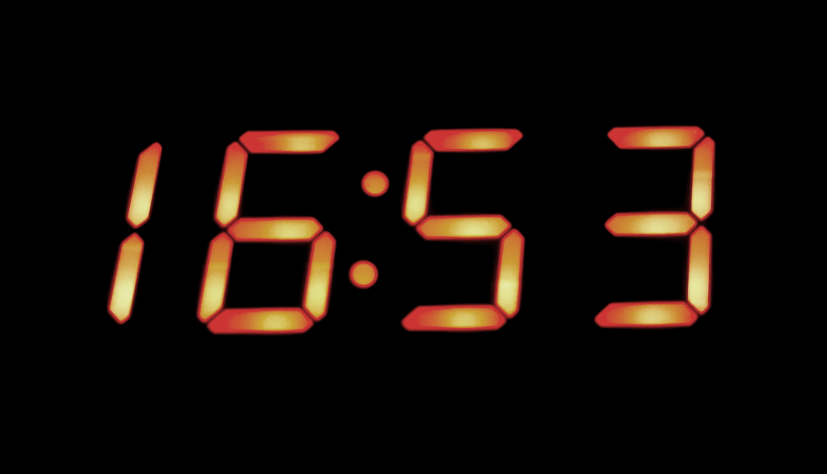
I also spent at least a few weeks determining what base to use. I was thinking about base 3, and base 8 for most of that time. What finally drew me to base 5 was when I started calculating out how many LEDs it would take to convey the number 24 ( For max hours in military time ). It takes exactly 2 LEDs to do this which I found to be perfectly succinct. Then, after realizing that 3 additional LEDs would easily allow me to show every minute value up to 59 it seemed strikingly elegant that the number of LEDs required to display both the hours and minutes ( 5 total ) was the same as the base I was using. This part of the project strangely seemed to design itself. It just felt right for the clock to be configured in this way. The more I thought about it, the more I realized that it was something I had to bring into existence as a functional art piece.

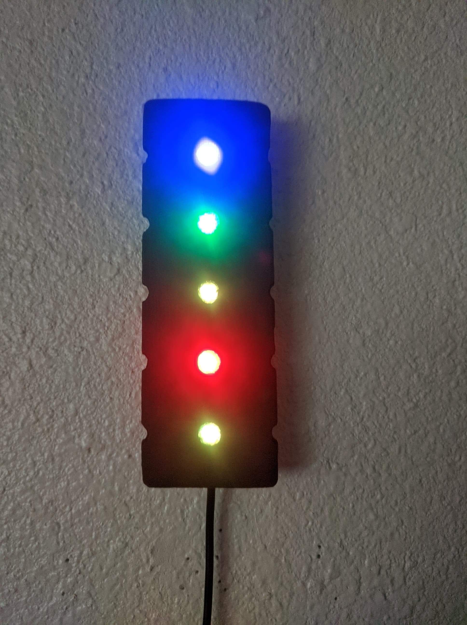
The next step was determining what colors should indicate the digits 4 through 0. What made the most sense to me was to use at least Red Green and Blue in that order. With Red being the most significant value of 4, Green being 3, and Blue as 2. I still needed to choose a value for 1, and since I like the color Purple I decided to go with that. The biggest challenge of choosing the digit colors was what to do with the digit 0. One option is to leave the LED off to indicate 0's, but in my experience with my binary clocks, I've found that having at least some amount of light on this digit can be very useful for reading these sorts of displays in the dark. I originally went with the color Orange, because I liked that the first letter of the color looked like the digit it represents. Although, in practice with the particular LED strips I have, I found it more easily discernible to use a dim Yellow for 0's. So the way I think about the final colorset is as RGBPY, or Red, Green, Blue, Purple, Yellow. The clock made a lot more sense to me after I committed these color/digit pairs to memory and I can now readily associate the colors I chose with the digit values that they represent.

The coding of this project is the part that took the least amount of time. I was able to re-use much of the code that I have used for previous esp8266 projects, although I did spend a couple of nights after work to make the code cleaner by moving certain parts of it to self-contained helper functions. The time setting portion is handled automatically using Network Time Protocol, so the esp8266 hops onto my local WIFI router and retrieves the current local time from the internet. It also syncs up with the NTP server regularly so that there isn't much drift. I wrote a helper function to account for daylight savings time, so that unlike with my other clock projects, I won't have to reflash the code twice a year for it to remain accurate. The settings for timezone, daylight savings time, the colorset, and everything else are defined in adjustable values up near the top of the code so that they can be adjusted easily by someone else ( Or more likely, me years from now ).

The final nicety with the code is that at 8 pm every night it turns the brightness down quite a bit so that the LEDs don't garishly illuminate a dark room. After 8 am the clock sets its brightness back to daytime mode. The full code can be downloaded here, and the meat of it follows below:
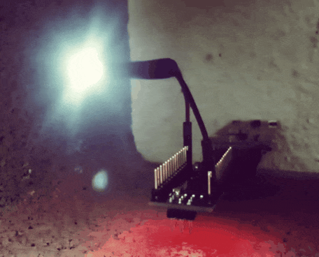
// Quinary RGBPY LED Clock
// Spike Snell 2020
//
// Add ESP8266 board from https://arduino.esp8266.com/stable/package_esp8266com_index.json
// ( File > Preferences, Tools > Board > Board Manager )

#include <NTPClient.h> // https://github.com/taranais/NTPClient
#include <FastLED.h> // https://github.com/FastLED/FastLED
#include <ESP8266WiFi.h>
#include <WiFiUdp.h>

// Define the number of leds
#define NUM_LEDS 5

// Define the data pin
#define DATA_PIN 4

// Set up the character arrays for the Wifi ssid and password
const char *ssid = "********";
const char *password = "********";

// Define the UTC Time offsets, these are for Central time in North America
const long winterOffset = -21600;
const long summerOffset = -18000;

// Define the DST Start and end Months and Days
const int dstMonthStart = 3;
const int dstDayStart = 8;
const int dstMonthEnd = 11;
const int dstDayEnd = 1;

// Define the bright and dim light intensity 0 - 255
const int bright = 88;
const int dim = 15;

// Define the hour that daylight roughly starts and ends
const int hourDayStarts = 8;
const int hourDayEnds = 20;

// Define the led digit colors
uint32_t color[] = {
0x151000, // 0, Dim Yellow
0xAA00AA, // 1, Purple
0x0000FF, // 2, Blue
0x005500, // 3, Green
0xFF0000 // 4, Red
};

// Define NTP Client to get the time
WiFiUDP ntpUDP;

// Set up the Network Time Protocol Client, update with fresh time every 10 minutes
NTPClient timeClient(ntpUDP, "85.21.78.23", winterOffset, 600000);

// Set up the leds array
CRGB leds[NUM_LEDS];

// Setup our sketch
void setup() {

// Connect to the wifi point
WiFi.begin(ssid, password);

// Wait for the wifi to be connected
while ( WiFi.status() != WL_CONNECTED ) {
delay(500);
}

// Start the time client
timeClient.begin();

// Add the leds array to the Fast Led Definition
FastLED.addLeds<NEOPIXEL, DATA_PIN>(leds, NUM_LEDS);

}

// Loop through this part every second
void loop() {

// Update the time client to get the current time
timeClient.update();

// Adjust for daylight savings time
adjustDst();

// Parse the current time and prepare all the led colors
parseTime();

// Show all the leds
FastLED.show();

// Wait for 1 second
delay(1000);

}

// Adjust for daylight savings time considerations
void adjustDst() {

// Extract date
String formattedDate = timeClient.getFormattedDate();

// Get the current month string
String month = formattedDate.substring(5, 7);

// Get the current day string
String day = formattedDate.substring(8,10);

// If we are within the defined daylight savings time period
if ( (month.toInt() > dstMonthStart && month.toInt() < dstMonthEnd) ||
(month.toInt() == dstMonthStart && day.toInt() > dstDayStart - 1) ||
(month.toInt() == dstMonthEnd && day.toInt() < dstDayEnd) ){

// Set summer time
timeClient.setTimeOffset(summerOffset);

}

// Else we must not be in daylight savings time
else {

// Set winter time
timeClient.setTimeOffset(winterOffset);

}

}

// Parse the current time and prepare all the led colors
void parseTime() {

// Create our character buffers
char timeBuffer[5];
char minuteBuffer[3];
char tempHourBuffer[2];
char tempMinuteBuffer[3];

// Set the leds bright if during the daytime
if ( timeClient.getHours() > hourDayStarts - 1 && timeClient.getHours() < hourDayEnds ) {

// Set leds to bright mode
FastLED.setBrightness(bright);

}

// Else set the led's to be dim because it is nighttime
else {

// Set leds to dim mode
FastLED.setBrightness(dim);

}

// Convert the current hours to base 5
itoa(timeClient.getHours(),tempHourBuffer,5);

// Convert the current minutes to base 5
itoa(timeClient.getMinutes(),tempMinuteBuffer,5);

// Pad 0's to the hour buffer and place it on the timeBuffer
sprintf( timeBuffer, "%02s", tempHourBuffer );

// Pad 0's onto the tempMinuteBuffer and place it on minuteBuffer
sprintf( minuteBuffer, "%03s", tempMinuteBuffer );

// Concatenate the timeBuffer and minuteBuffer
strcat(timeBuffer, minuteBuffer);

// Iterate over the timeBuffer and set all the leds
for (int i = 0; i < strlen(timeBuffer); i++) {

// Switch on the2 current timeBuffer digit and set each led's color
switch(timeBuffer[ i ]) {
case '0' :
leds[ i ] = color[0];
break;
case '1' :
leds[ i ] = color[1];
break;
case '2' :
leds[ i ]= color[2];
break;
case '3' :
leds[ i ] = color[3];
break;
default :
leds[ i ] = color[4];
}

}

}
Another part of this project that took quite a bit of time was determining how I wanted to arrange and display the LEDs physically. I've had a lot of prototypes, from just the LED strip laid out loose, or on a strip of cardboard, to putting them on popsicle sticks. My current favorite version is where I have eliminated the LED strip and wired individual nanopixels directly into a strip of pegboard that I painted black. With a little bit of hot glue smushed into the pegboard holes ( and then roughed up a bit with a nail ) very pleasing diffused colors can be generated.

I've had one of these quinary clocks in place prominently in my living room for so long now that it is starting to feel less like a novelty and has instead become a permanent function of the wall itself. It is one of the main clocks that I look to throughout the day to determine what time it is. I've had people see it many times without realizing that it was a clock who were subsequently astonished when inquiring and finding out its secret use. The clock comes across much like an amorphous colorful art installation if you don't know what it is. But, when you start explaining that it is a timepiece and how to read it, that is when they start looking at you like you're a little crazy. Luckily, my girlfriend is also interested in programming and computer science, so she was able to start reading the new clock pretty naturally within a couple of days.

I strongly like this quinary clock. It turned out a lot more elegant than I first imagined it would, and it has become a visually intriguing yet useful part of my living environment that I would very much miss if absent. Unlike most of the other projects that I set up, have fun with for a few weeks, and then set aside, I feel confident that this one will be staying up indefinitely.
add comment ( 2012 views )   |  permalink   |  $star_image$star_image$star_image$star_image$star_image ( 3 / 2753 )
Wifi NTP Clock ( ESP8266 with TM1637 ) 
Sunday, April 5, 2020, 15:58
Posted by Administrator


My latest passion project incorporates a cheap Wemos D1 Mini clone board ( ~2$ each on eBay ) with integrated wifi along with a TM1637 4-Digit Led display module ( ~ $1 each ) to create an incredibly accurate self-adjusting wifi clock. I had previously been using 4-Digit displays by individually addressing all the necessary inputs, but it takes a whole ratking of wires to do that and the cost savings are negligible compared to the TM1637 modules that can be found overseas.

The Wemos D1 Mini clones have become my go-to board for projects like these both because of their low cost and versatility. The Digispark boards I sometimes use still have them beat on price, but only by about 60 cents or so, and those don't have wifi so they wouldn't be suitable for this project.

The code is very straightforward after all the necessary board and module libraries are gathered and can be found below:
// Add ESP8266 board from https://arduino.esp8266.com/stable/package_esp8266com_index.json ( File > Preferences, Tools > Board > Board Manager )

#include <TM1637Display.h> // https://github.com/avishorp/TM1637
#include <NTPClient.h> // https://github.com/arduino-libraries/NTPClient
#include <ESP8266WiFi.h>
#include <WiFiUdp.h>

// Set up the character arrays for the Wifi ssid and password
const char *ssid = "********";
const char *password = "********";

// Set the UTC Time offset in seconds
// const long utcOffsetInSeconds = -21600;
const long utcOffsetInSeconds = -18000;

// Define NTP Client to get the time
WiFiUDP ntpUDP;

// Set up the Network Time Protocol Client, update with fresh time every 10 minutes
NTPClient timeClient(ntpUDP, "85.21.78.23", utcOffsetInSeconds, 600000);

// Module connection pins (Digital Pins)
#define CLK 5
#define DIO 4

// Set up the TM1637 Display
TM1637Display display(CLK, DIO);

void setup() {

// Set the brightness of the display ( 0xff is brightest )
display.setBrightness(0x1a);

// Connect to the wifi point
WiFi.begin(ssid, password);

// Wait for the wifi to be connected
while ( WiFi.status() != WL_CONNECTED ) {
delay(500);
}

// Start the time client
timeClient.begin();

}

void loop() {

// Update the time client to get the current time
timeClient.update();

// Display the hours
display.showNumberDecEx(timeClient.getHours(), 0b11100000, true, 2, 0);

// Display the minutes
display.showNumberDecEx(timeClient.getMinutes(), 0b11100000, true, 2, 2);

}
I'm running it without an enclosure but have carefully soldered the necessary wires in place on the back of the board and then have hot-glued the whole assembly together such that the front-facing side of the clock fully obscures the D1 Mini behind it:


The mounting holes on the 4-Digit display make for easy attaching to the wall with push pins, but the unit can also just be set by itself on a desk because it is self-supporting. It consumes little power, and I've run it successfully on some portable battery packs for many days. Most of the time I leave it nestled into a piece of driftwood in the bedroom.

I initially ran into an issue where the time would sometimes stop getting set and start to drift. I was able to correct this by using the specific IP address of the NTP ( Network Time Protocol ) server I like best, instead of relying on a DNS to get the IP for me. I suspect that after enough reconnects the DNS handler stops working correctly and causes the library I'm using to fail after enough attempts. Since changing to a set IPv4 address I've had no issues with the clock at all and have found it to be extremely accurate even when running for many months in a row.

The real beauty of this project is its simplicity. Plug in the clock, it sets itself, you're done. Altogether the cost of all wires, hotglue, solder, and modules for this project is well below $4. A future improvement I'd like to make to this would be to more intelligently handle daylight savings time because right now the board has to be re-flashed every time that this is in effect.

Comments are very much welcome.
add comment ( 5012 views )   |  permalink   |  $star_image$star_image$star_image$star_image$star_image ( 3.1 / 3940 )
Morse Code Tao Te Ching Flashing on the Arduino 
Saturday, August 31, 2019, 14:44
Posted by Administrator


This year I have been experimenting quite a bit with the Arduino platform. I love how Arduino clones are much cheaper than Raspberry Pi’s and only cost me around 2 dollars each from China. Arduinos also consume very little power and run for many days on my rechargeable external battery packs.

Long ago I created a blinking morse code light on a Raspberry Pi which slowly flashed the Tao Te Ching. It was a relatively straightforward process as there is far more than enough storage available on virtually any Micro Sd card to hold even the largest of books. 
 
My first true Arduino project was to remake my morse code Tao Te Ching light. Getting the Arduino to flash morse code was straightforward and lots of people have worked up examples that got me started. I made many modifications to some code I found online, and eventually got the Litany Against Fear from Dune to flash out on a small white LED:

// Message
byte m[] = "I MUST NOT FEAR. FEAR IS THE MIND-KILLER. FEAR IS THE LITTLE-DEATH THAT BRINGS TOTAL OBLITERATION. I WILL FACE MY FEAR. I WILL PERMIT IT TO PASS OVER ME AND THROUGH ME. AND WHEN IT HAS GONE PAST I WILL TURN THE INNER EYE TO SEE ITS PATH. WHERE THE FEAR HAS GONE THERE WILL BE NOTHING. ONLY I WILL REMAIN.";

// Pin to flash
int pin = 13;

// Tempo
// 240 ~5wpm
// 120 ~10wpm
// 80 ~15wpm
int t = 240;

// Setup the output pin
void setup () {
pinMode(pin, OUTPUT);
}

// Perform the dits
void d() {
digitalWrite(pin, HIGH);
delay(1 * t);
digitalWrite(pin, LOW);
delay(1 * t);
}

// Perform the das
void da() {
digitalWrite(pin, HIGH);
delay(3 * t);
digitalWrite(pin, LOW);
delay(1 * t);
}

// Define the pattern of dits and das for each letter
void morse(byte l) {
if (l == 'A' or l == 'a') {d(); da();}
else if (l == 'B' or l == 'b') {da(); d(); d(); d();}
else if (l == 'C' or l == 'c') {da(); d(); da(); d();}
else if (l == 'D' or l == 'd') {da(); d(); d();}
else if (l == 'E' or l == 'e') {d();}
else if (l == 'F' or l == 'f') {d(); d(); da(); d();}
else if (l == 'G' or l == 'g') {da(); da(); d();}
else if (l == 'H' or l == 'h') {d(); d(); d(); d();}
else if (l == 'I' or l == 'i') {d(); d();}
else if (l == 'J' or l == 'j') {d(); da(); da(); da();}
else if (l == 'K' or l == 'k') {da(); d(); da();}
else if (l == 'L' or l == 'l') {d(); da(); d(); d();}
else if (l == 'M' or l == 'm') {da(); da();}
else if (l == 'N' or l == 'n') {da(); d();}
else if (l == 'O' or l == 'o') {da(); da(); da();}
else if (l == 'P' or l == 'p') {d(); da(); da(); d();}
else if (l == 'Q' or l == 'q') {da(); da(); d(); da();}
else if (l == 'R' or l == 'r') {d(); da(); d();}
else if (l == 'S' or l == 's') {d(); d(); d();}
else if (l == 'T' or l == 't') {da();}
else if (l == 'U' or l == 'u') {d(); d(); da();}
else if (l == 'V' or l == 'v') {d(); d(); d(); da();}
else if (l == 'W' or l == 'w') {d(); da(); da();}
else if (l == 'X' or l == 'x') {da(); d(); d(); da();}
else if (l == 'Y' or l == 'y') {da(); d(); da(); da();}
else if (l == 'Z' or l == 'z') {da(); da(); d(); d();}
else if (l == '1') {d(); da(); da(); da(); da();}
else if (l == '2') {d(); d(); da(); da(); da();}
else if (l == '3') {d(); d(); d(); da(); da();}
else if (l == '4') {d(); d(); d(); d(); da();}
else if (l == '5') {d(); d(); d(); d(); d();}
else if (l == '6') {da(); d(); d(); d(); d();}
else if (l == '7') {da(); da(); d(); d(); d();}
else if (l == '8') {da(); da(); da(); d(); d();}
else if (l == '9') {da(); da(); da(); da(); d();}
else if (l == '0') {da(); da(); da(); da(); da();}
else if (l == '.') {d(); da(); d(); da(); d(); da();}
else if (l == ',') {da(); da(); d(); d(); da(); da();}
else if (l == '?') {d(); d(); da(); da(); d(); d();}
else if (l == '\'') {d(); da(); da(); da(); da(); d();}
else if (l == '!') {da(); d(); da(); d(); da(); da();}
else if (l == '/') {da(); d(); d(); da(); d();}
else if (l == '(') {da(); d(); da(); da(); d();}
else if (l == ')') {da(); d(); da(); da(); d(); da();}
else if (l == '&') {d(); da(); d(); d(); d();}
else if (l == ':') {da(); da(); da(); d(); d();d();}
else if (l == ';') {da(); d(); da(); d(); da(); d();}
else if (l == '=') {da(); d(); d(); d(); da();}
else if (l == '+') {d(); da(); d(); da(); d();}
else if (l == '-') {da(); d(); d(); d(); d(); da();}
else if (l == '_') {d(); d(); da(); da(); d(); da();}
else if (l == '"') {d(); da(); d(); d(); da(); d();}
else if (l == '$') {d(); d(); d(); da(); d(); d(); da();}
else if (l == '@') {d(); da(); da(); d(); da(); d();}

// Plus the two below equals a delay of 7 tempos for a space
if (l == ' ') {delay(5 * t);}

// Delay of 3 tempos, 2, plus the delay after a character
delay(2 * t);

}

// Loop through the message
void loop () {

// For each character in the message
for (int g = 0; g < sizeof(m); g++) {

// Flash the morse equivalent for this letter
morse(m[g]);

}

}

The real challenge was in getting an entire book to fit on an Arduino. Most standard Arduino’s such as the Arduino Nano clones that I’m using have roughly 32K of storage space for holding programs. You get even less than this in reality since a typical bootloader for the Arduino takes .5K – 2K of the space before you even load your code on there. Even though the morse code flashing instructions I put together are relatively small, there was still not nearly enough space left to hold my favorite copy of the Tao Te Ching translated by Stephen Mitchell.

His translation is around 37.32K and my original hope was that if I removed all the line breaks, and most of of the punctuation that I could get it to fit somehow. However, after adding in the additional code for flashing the LED and the bootloader, it became apparent that there was just no way this was going to work. I then pondered over it all for a couple of days.

Compression is the natural solution to this problem. I was able to find a wonderfully up to date text compression utility called Shox96. It is a hybrid entropy and dictionary encoder and the author has put together a great white paper on the design which is well worth reading. It also has a version which works great at compressing short strings into the Arduino program memory.

After compressing Stephen Mitchell’s translation of the Tao Te Ching with Shox96 and then decompressing one chunk at a time and feeding that into my morse code flashing program it all worked perfectly. I had the entire book flashing before my eyes. 
 
There was even plenty of free space left over. So I decided to make things a lot harder and use this public domain translation of the Tao Te Ching by John H. McDonald which is ~45.70K in size when not compressed. After compressing it… it did not fit on the Arduino anymore.

I continued to poke at it and eventually realized that Shox96 encoding is more efficient when the lines of text are long. I then went through the full text manually and increased the line sizes to mostly be full sentences. Compressing this version got it all plenty small enough and I finally considered the project to be finished.

I left the light blinking for many weeks running off of the USB port on the side of my office monitor. At the slow speed I set it at it takes longer than a day to run through the entire book, at this point it loops and starts from the beginning. I left serial debugging on, so if you monitor the serial output of the device you can watch it print each character to the screen as it flashes. This looked especially nice when paired with outputting to a CRT television. I ran it this way for many days as well. 
 
This project helped me get quite a bit more familiar with Arduino’s and making use of additional libraries when working on sketches. The final flashing art piece also got me much better at sight-reading morse code which was a nice bonus.
 
The full code for this project is available here. Let me know if you can think of any other great books that would benefit from this sort of harassment.
add comment ( 2577 views )   |  permalink   |  $star_image$star_image$star_image$star_image$star_image ( 3 / 3193 )

| 1 | 2 | 3 | 4 | 5 | 6 | 7 | 8 | 9 | Next> Last>>